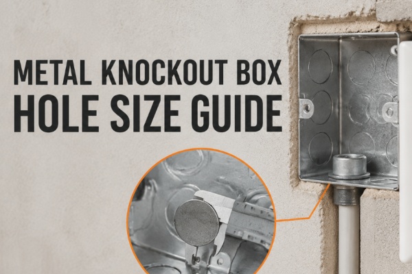
A metal knockout box hole size should be selected according to the conduit connector, cable gland or cable clamp that passes through the box—not simply according to the cable diameter. Conduit nominal size, fitting thread, required mounting hole and actual knockout diameter are related measurements, but they are not necessarily the same number.
A common example is a North American 1/2-inch conduit knockout. The “1/2 inch” is a conduit trade size, while the corresponding nominal knockout diameter is approximately 0.875 inch, or 22.2mm. Treating it as a 12.7mm hole would result in an incorrect specification.
Metric systems create a different source of confusion. A 20mm conduit entry, an M20 cable gland and a cable with a 20mm outside diameter do not describe the same requirement. This guide explains how these dimensions relate and how to read knockout specifications correctly.
Table of Contents
- What Does a Knockout Size Refer To?
- Four Measurements That Should Not Be Confused
- Metric Knockouts vs Imperial Trade Sizes
- Imperial Conduit Knockout Size Chart
- Standard, Concentric and Eccentric Knockouts
- How to Match a Knockout to a Fitting
- Why Knockout Position and Spacing Matter
- How to Measure an Unknown Knockout
- Knockout Removal and Edge Protection
- Common Knockout Size Mistakes
- Frequently Asked Questions
What Does a Knockout Size Refer To?
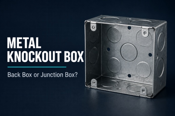
A knockout is a partially formed section in the wall of a metal electrical box. It remains attached until an entry is needed. After the selected section is removed, an appropriate cable or conduit fitting is installed in the resulting opening.
The phrase “knockout size” can be used in two different ways:
- Nominal system size: the trade designation associated with the conduit or fitting, such as 1/2 inch, 3/4 inch, 20mm or 25mm.
- Physical hole diameter: the actual diameter of the opening after the knockout has been removed.
These two values should not automatically be treated as equal. A supplier may list a box as having “1/2-inch knockouts” even though the physical openings are considerably larger than 1/2 inch. In this case, the listing identifies the compatible conduit trade size rather than the actual hole diameter.
For an unambiguous product specification, state both the fitting system and required opening where necessary.
Specification example: Six knockouts for 20mm conduit fittings; final hole diameter and tolerance according to the approved fitting specification.
Four Measurements That Should Not Be Confused
A correct metal knockout box specification may involve four separate measurements.
| Measurement | What It Describes | Why It Matters |
|---|---|---|
| Cable outside diameter | The overall diameter of the cable entering the box | Used to select the gland or clamp sealing range, not normally the knockout directly |
| Conduit nominal size | The named size of the conduit system | May be a trade designation rather than the conduit’s exact outside diameter |
| Fitting entry size | The thread, stem or body that passes through the box wall | Determines the opening and locknut arrangement required at the box |
| Finished hole diameter | The actual diameter after the knockout is removed | Must provide suitable clearance without becoming too large for secure fitting engagement |
The complete relationship can be understood as:
Cable → Gland or Conduit → Connector → Required Mounting Hole → Metal Knockout Box
Starting with the cable alone skips several important components. A cable gland, for example, is selected partly by its cable clamping range and partly by its enclosure-entry thread. Two glands with the same M20 thread can have different cable clamping ranges.
Metric Knockouts vs Imperial Trade Sizes
Metric and North American trade-size systems should be treated as separate specification systems. A simple inch-to-millimetre conversion does not establish compatibility.
Metric Conduit Entries
A product described as having 20mm or 25mm knockouts is generally intended for fittings within a corresponding metric conduit system. However, the final hole diameter, tolerance and connector design should still be verified from the fitting specification.
The expression “20mm knockout” may refer to the nominal conduit system rather than guaranteeing that every finished opening measures exactly 20.00mm. Box-wall thickness, knockout tolerance and the connector’s mounting method also affect the required fit.
Metric Cable Gland Threads
An M20 cable gland has a metric entry thread. It does not mean that the gland is intended for a cable with a 20mm outside diameter. The cable clamping range is a separate value and may be much smaller.
The required mounting hole may also be slightly larger than the nominal thread. For example, one documented M20 entry component specifies a permissible bore of 20.0–20.7mm. This is a product-specific requirement rather than a universal dimension for every M20 gland.
Imperial Conduit Trade Sizes
In North American electrical catalogs, 1/2-inch, 3/4-inch and 1-inch conduit sizes are trade designations. They should not be read as literal knockout diameters.
For example, a nominal 1/2-inch conduit knockout is approximately 0.875 inch in diameter. This is about 22.2mm, not 12.7mm. It is also not automatically interchangeable with an M20 opening.
| Description | What the Number Means | What It Does Not Mean |
|---|---|---|
| 20mm conduit knockout | A metric conduit-entry designation | A universal opening for every M20 gland |
| M20 cable gland | The gland’s metric entry-thread size | A cable clamping range of 20mm |
| 1/2-inch conduit knockout | A North American conduit trade size | A physical hole diameter of 1/2 inch |
| 20mm cable diameter | The cable’s physical outside diameter | The correct knockout or gland thread size |
Imperial Conduit Knockout Size Chart
The following values show how common conduit trade sizes relate to nominal knockout diameters. They are reference dimensions rather than a replacement for the selected box and fitting drawings.
| Conduit Trade Size | Nominal Knockout Diameter | Approximate Metric Diameter |
|---|---|---|
| 3/8 inch | 0.625 inch | 15.9mm |
| 1/2 inch | 0.875 inch | 22.2mm |
| 3/4 inch | 1.109 inches | 28.2mm |
| 1 inch | 1.375 inches | 34.9mm |
| 1-1/4 inches | 1.734 inches | 44.0mm |
| 1-1/2 inches | 1.984 inches | 50.4mm |
| 2 inches | 2.469 inches | 62.7mm |
These are nominal reference values. Manufacturing tolerances, fitting construction, box listing and local requirements must be checked before use. The metric values are mathematical conversions of the inch dimensions, not equivalent metric fitting sizes.
Standard, Concentric and Eccentric Knockouts
Knockout size is also influenced by the knockout structure. A single knockout provides one opening size, while multi-ring designs can provide several size options from one box position.
| Knockout Type | Structure | Main Advantage | Important Check |
|---|---|---|---|
| Standard knockout | One removable section for one opening size | Simple size identification and removal | The selected fitting must match that fixed opening |
| Concentric knockout | Two or more rings sharing the same center | Several entry sizes can occupy one position | The required ring must be removed without damaging the remaining structure |
| Eccentric knockout | Multiple rings with offset centers | Provides more than one size while shifting the final opening position | Connector clearance and remaining ring integrity |
| Combination knockout | A manufacturer-specific multi-size entry design | Allows one box model to support more fitting options | The catalog’s size notation and removal instructions |
Abbreviations such as “KO,” “CKO” or “TKO” may appear in electrical box catalogs, but their exact meaning should be checked against the manufacturer’s legend. A listing such as “1/2–3/4 combination KO” generally indicates that one entry position can provide either size. It does not mean the finished hole should be measured halfway between them.
Bonding Is a Separate Consideration
Concentric and eccentric knockouts create a more complex metal path than a single solid opening. Their suitability for grounding and bonding should be based on the product certification, installed fitting and applicable electrical rules—not on appearance alone.
Different requirements may apply to metallic outlet boxes, service equipment and other electrical enclosures. If a ring is damaged, loosened or removed incorrectly, the original bonding performance should not be assumed to remain unchanged.
How to Match a Knockout to a Conduit or Cable Fitting
Reliable matching should follow the complete entry assembly rather than one isolated dimension.
- Identify the wiring method. Determine whether the box will receive conduit, a cable gland, a cable clamp, flexible conduit or another approved entry component.
- Confirm the conduit or cable. Record the conduit system and nominal size, or the cable’s actual outside diameter and construction.
- Select the connector or gland. Check its conduit compatibility, cable clamping range, thread or entry-stem size.
- Find the required mounting hole. Use the fitting manufacturer’s recommended hole diameter and tolerance.
- Check box-wall compatibility. Confirm that the connector can engage correctly through the metal thickness.
- Check locknut and washer coverage. The retaining components need enough flat metal around the opening.
- Verify internal projection. A connector that fits the hole may still extend too far into a shallow box.
- Confirm installation requirements. Bonding, bushings, sealing washers and other components depend on the system and installation environment.
Practical principle: the correct knockout is the opening specified for the approved entry fitting—not the opening that merely looks close to the cable or conduit diameter.
Why Knockout Position and Spacing Matter
Two metal knockout boxes can provide the same hole sizes but behave differently during installation because the knockouts are arranged differently.
Important layout checks include:
- Conduit direction: side, rear and base entries suit different wiring routes.
- Cable bending space: an entry close to the device body may leave insufficient room for conductors to turn.
- Connector projection: the fitting may extend into the space needed by the switch, socket or terminals.
- Locknut clearance: adjacent fittings need enough space for locknuts and installation tools.
- Mounting-lug interference: a connector should not conflict with fixed or adjustable device lugs.
- Support-bar interference: wider boxes may contain a center support bar that affects the available entry area.
- Wall clearance: a rear connector may require more space behind the box than the wall cavity provides.
- Edge distance: enough material must remain around the hole to support the fitting securely.
More knockouts do not automatically make a box better. A smaller number of correctly positioned entries can be more useful than many openings that conflict with the device, fittings or planned conduit route.
For a broader discussion of entry quantity and placement, see How to Choose the Right Knockout Configuration.
How to Measure an Unknown Knockout
When an existing box has no clear knockout marking, use a controlled identification process.
- Look for a model number or drawing. Manufacturer documentation is usually more reliable than estimating from appearance.
- Check for stamped markings. Some boxes identify conduit trade sizes next to the entries.
- Determine the likely specification system. Establish whether the box uses metric sizes, North American trade sizes or another regional system.
- Identify the knockout type. A single, concentric or eccentric design must be interpreted differently.
- Measure the finished opening where possible. The removable disc itself may not represent the exact usable hole diameter.
- Compare the result with the fitting drawing. Confirm the required hole rather than relying on a general conversion chart.
- Check the retaining components. Verify that the connector shoulder, locknut and washer cover the opening properly.
A vernier caliper can help measure a clean finished hole, but measurement alone does not establish certification or compatibility. If the box is already installed or energized, inspection and modification should only be performed under appropriate safe-working procedures by a qualified person.
Knockout Removal and Edge Protection
Correct knockout selection can still be undermined by poor removal. A knockout should create a controlled opening without distorting the surrounding box wall.
- Remove only the entry required for the planned cable or conduit route.
- Support the box so the surrounding panel is not bent during removal.
- Use a suitable tool and follow the box manufacturer’s removal method.
- When working with a multi-ring knockout, avoid loosening the larger ring if the smaller opening is required.
- Inspect the finished opening for torn metal, burrs and sharp edges.
- Fit the appropriate connector, gland, clamp, bushing or edge-protection component for the wiring method.
- Close any previously opened but unused entry with a suitable knockout seal or plug.
- Check the completed entry for mechanical security, cable protection and required bonding.
If an opening is too small, enlarging it with an appropriate hole-making tool may be possible for some box designs. However, uncontrolled drilling or filing can change edge quality, hole position, coating condition, box strength and certification. Using a box with the correct factory knockout is often the clearer solution.
Common Knockout Size Mistakes
| Mistake | Why It Happens | Possible Result | Better Method |
|---|---|---|---|
| Selecting the hole from cable diameter | The gland or connector is ignored | The fitting cannot be installed or cannot clamp correctly | Select the entry fitting first |
| Treating 1/2 inch as a 12.7mm hole | Trade size is mistaken for physical diameter | The specified knockout is much too small | Use the conduit knockout chart for the selected system |
| Treating M20 and 1/2 inch as identical | Both appear to be small entry sizes | Thread or hole mismatch | Keep metric and trade-size systems separate |
| Measuring only the removable disc | The knockout has not been opened | Incorrect estimate of the finished hole | Use the drawing or measure a clean finished opening |
| Damaging the outer ring of a concentric knockout | Too much force is applied during removal | The final opening becomes oversized or unstable | Use controlled removal suited to the knockout design |
| Checking diameter but ignoring position | The box is reviewed only from a hole-size table | The connector conflicts with the device or support structure | Review the complete box layout |
| Leaving an unused opening unsealed | The wrong knockout was removed | Loss of enclosure integrity and accidental access | Install a suitable knockout seal or replace the box |
| Assuming every knockout provides a bonding path | Metal-to-metal contact is treated as sufficient evidence | Installation may not meet the required bonding method | Check the product listing and applicable rules |
Frequently Asked Questions
What is the actual hole size for a 1/2-inch conduit knockout?
A commonly referenced nominal diameter is 0.875 inch, or approximately 22.2mm. The 1/2-inch label is the conduit trade size, not the physical hole diameter. Confirm the selected box and connector specifications before installation.
Is a 20mm knockout the same as a 1/2-inch knockout?
No. A metric 20mm entry and a North American 1/2-inch conduit knockout belong to different sizing systems. A nominal 1/2-inch knockout is approximately 22.2mm in diameter, while an M20 or 20mm fitting may require an opening closer to its metric thread or fitting specification.
Does an M20 cable gland fit a 20mm cable?
Not necessarily. M20 identifies the gland’s entry thread. The acceptable cable outside-diameter range is a separate specification and varies between gland designs.
Can a knockout be enlarged?
Some boxes can accept a correctly produced additional or enlarged opening, but this must not be assumed. Hole position, edge distance, box strength, surface protection, bonding and product approval may be affected. Follow the box and fitting manufacturers’ instructions and applicable installation requirements.
What should be done if the knockout is too large?
Do not improvise with an undersized connector or loose locknut. Use an approved reducing component or entry adapter where permitted, close the opening with a suitable seal, or select a box with the correct knockout.
What is a concentric knockout?
A concentric knockout contains two or more removable rings with the same center. Removing different rings creates different opening sizes at one box position.
Can an opened knockout be left unused?
An unused opening should be closed with a suitable knockout seal or plug that matches the opening and enclosure requirements. Leaving it open can reduce enclosure integrity and allow accidental access to internal wiring.
Should knockout size be specified before the box is manufactured?
Yes. For an accurate metal knockout box specification, confirm the hole size, tolerance, quantity, panel location and center position. A drawing should also show nearby lugs, support bars and mounting features.
Conclusion
A metal knockout box hole size is part of a complete cable-entry system. The cable diameter helps determine the gland or clamp, the conduit size helps determine the connector, and the connector specification determines the required box opening.
The most important distinction is that a nominal size is not always a physical diameter. A 1/2-inch conduit knockout is not a 1/2-inch hole, an M20 gland is not automatically suitable for a 20mm cable, and a 20mm metric entry is not a direct substitute for a 1/2-inch trade-size knockout.
Before selecting or specifying a box, confirm the sizing system, fitting type, required finished hole, knockout position, box thickness, internal clearance and applicable installation requirements. This provides a more reliable result than selecting the knockout from the cable diameter or product name alone.